source: Wikipedia
Additive layer technology more commonly known as the 3D printing or layer by layer manufacturing technology is the most discussed and used (at small level) manufacturing method now a days. As engineers are trying to manufacture more and more products through additive layer manufacturing so in this post we will try to select a an additive layer manufacturing process for engine cylinder block by working on following steps
1. Study the current Manufacturing Process
2. Select one additive layer manufacturing process
3. Study the new manufacturing process
4. Compare the present and new manufacturing processes
5. Conclude the result about the additive layer manufacturing of engine cylinder block
1.0 Introduction
Additive layer manufacturing process work opposite to the conventional subtractive method was parts are manufacture by removing the material from a work piece. In additive layer manufacturing the parts are made by combining the successive layer of material one over the other under a control environment [1]. Initially this method was mostly used for rapid prototyping but with time the manufacturer realized its importance and own they are used for the production of functional products [2]. Currently the additive layer manufacturing is basically used for the production of the equipment used in aerospace and high performance cars because of very high cost of the equipment used in this process [3].
Here a brief study about the suggestion of an additive layer manufacturing for the manufacturing of cylinder block of a V-6 engine has been conducted here. Before suggestion of the ALM process, the current manufacturing process and material requirements will be discuss along with the brief discussion of the product.
1.1 Cylinder Block
An engine block is the core of the engine which houses nearly all of the components required for the engine to function properly. The block is typically arranged in a “V,” inline, or horizontally-opposed (also referred to as flat) configuration and the number of cylinders range from either 3 to as much as 16. Because engine blocks are a critical component of an engine, it must satisfy a number of functional requirements. These requirements include lasting the life of the vehicle, housing internal moving parts and fluids, ease of service and maintenance, and withstand pressures created by the combustion process [4].
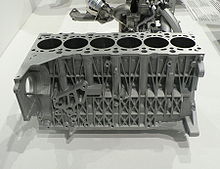
source: Wikipedia
Figure 1 Cylinder Block of IC Engine
1.2 Material for Cylinder Block
Following are some of the properties that a material should have in order to process it for manufacturing of cylinder block [5]
• Cheap
• Good Cast ability
• Good impressions
• Good Machine ability
• Rigid and strong
• Good abrasion resistance,
• Good corrosion resistance,
• High thermal expansion,
• High thermal conductivity,
• Low density.
Some of the material that are already in use in different manufacturing organization for production of cylinder block are cast iron, aluminum alloy and magnesium alloy. Aluminum alloys are now mostly used for high performance in light vehicle due to its low density and high strength [4] [8].
1.3 Manufacturing Process for Cylinder Block
There are number of manufacturing processes been used by different companies like Honda is using pressure die casting [6] and BMW is using sand casting [7] for their cylinder block production. Many other processes like machining from solid and lost form process are also being processed in different companies. Selection of the process really depends on the material and functional requirements of the engine cylinder block.
2.0 Current Manufacturing Process of Cylinder Block
The manufacturing process that will be discussed here is the sand casting and data mention below is being taken from the discovery channel documentary that show the complete manufacturing process of V-6 cylinder block [8].
Manufacturing process starts with the preparation of the sand and glue mixture that will be used for the production of cores. A single mold for a cylinder block is made up of 18 different cores and all are made for the master pattern made of steel. There is one main core with which all other 17 cores are attached. Iron liners are placed in the bores of the cylinder bore core, this help avoid abrasion. Some of the cores have to be glue to improve the strength and prevent the braking while assembling. Process of making and assembling and the cores are completely automated which decrease the time but increase the cost of operation.
After mold is complete the aluminum alloy ingots are melted in the gas fired furnace where temperature ranges up to 800 degree centigrade. Mold bores are heated with the electric current because the melted aluminum alloy bounds better with the hot metal. Molten aluminum alloys are feed from the bottom of the mold to avoid the oxide formation and can be a problem when molten material is feed from the top of the mold.
After the solidification the mold is place in the oven can thermal sand reclaim oven where it spend six hours to dissolve al the glue and recover all the sand. Sand remains inside the cylinder block is removed by tilting the block sidewise. Extra material in the shape of riser will be removed by the help of CNC machines. CNC machines will be used to do the finishing process of the cylinder block.
Process up till now is a general process for the production of the every engine cylinder block. Further detailing and finishing will be done according to the use of the cylinder block. After completing the process a visual test is conducted to check for any defect present in the product.
3.0 Current Manufacturing Process Steps
Following are the steps arranged in the sequence for the manufacturing of engine cylinder block as explained in the above [8]
1. CAD Drawing
2. Mater Pattern Preparation
3. Preparing Sand and Glue Mixture
4. Core Production
5. Cores Assembly
6. Melting Aluminum
7. Pouring
8. Sand Recovery Oven
9. Primary Machining
10. Final Machining
3.1 CAD Drawings
First step is to create the detail CAD drawing of the engine cylinder block and then divide it into different section according to the manufacturing process to manufacture the master pattern of each section. This step required highly skilled labor and good CAD software which not cost much. Time of this process is usually in days and cost of the process is low to moderate
3.2 Master Pattern
Master pattern is required for each sand core used to make a complete sand mold for the casting a one complete engine cylinder block. There are 18 total master patterns, one for each core. Creating a master pattern required a third party because manufacturing master pattern required highly skilled labor and expansive machinery. Manufacturing time is usually in days for a single master pattern, so manufacturing 18 master patterns required at least 4-5 month. Cost of this process is very high but it is one time process [9].
3.3 Preparing Sand and Glue Mixture
A separate mixing machine is used for the preparing the sand and glue mixture. Quality of the mixture is really important as this thing define the surface finish and some defects in the final product [10]. Sand and glue are mixed in predetermined quantity due to which this step required low labor skills and have low operation cost but is a continuous process because new mold is required every time.
3.4 Cores Production
To make a core, sand and glue mixture is blows into the cavity having master pattern. Here the sand and glue get hard with the help of gas which activities the hardener due to which sand takes the shape of the master pattern. This process is fully automatic which increase the rate of production but this come at increase cost in term of robots installation and operation [8]. This process of core making is continuous process because core need to broke in order to remove the cylinder block [10].
3.5 Core Assembly Line
There is one master core which the other 17 core are attached to make a single mold for the cylinder block casting. Process of the cores assembly is done with the help of robots [8] and it’s a continuous process because a new mold is requiring for every new casting.
3.6 Melting Aluminum Alloy
Aluminum alloy ingots are placed inside the gas fired furnace where temperature is about 800 degree centigrade. This process required careful handling due molted metal but this is continuous and a low cost process.
3.7 Pouring
In manufacturing of engine cylinder block the process of pouring the molten metal for filling the mold cavity is done from the bottom to avoid the formation of oxide [8]. This process has usually had low labor and equipment and processing cost because of its automation.
3.8 Sand Recovery Oven
After the solidification the mold is place in the sand recovery oven for six hours which dissolve all the glue present in the sand due to which all the sand is recovered. Sand present inside the cylinder block cavity can be removed my tilting the cylinder block side wise with the help of robotics [8]. This preprocess usually have low labor and processing cost associated with it because it can be done on many cylinder block molds in single time.
3.9 Primary Machining
After engine cylinder block is obtain form the sand recovery oven the process of machining is done to remove all the extra material present in the form of runner and riser and to provide some finishing to the engine cylinder block [8]. This process is usually done on the CNC machine have high equipment cost, and required skilled labor for processing but the high processing speed make it best for mass production processes [9].
3.10 Final Machining
Final machine is done by highly precise CNC machines due to high level of dimensional tolerance required for piston bores and all other parts. This process is usually done on the CNC machine have high equipment cost, and required skilled labor for processing but the high processing speed make it best for mass production processes [9].
4.0 Additive Layer Manufacturing Processes
Additive layer manufacturing technique manufacture a 3D product by adding layers of the materials one above the other that why this process is also known as layer by layer manufacturing. On the basis of the phase of the raw material used the additive layer manufacturing can be divided into three types 1. Liquid base processes 2. Powder base processes and 3. Solid base processes. Each of these processes is further divided into subtypes shown below
• Liquid Based Processes
1. Stereolithography Apparatus(SLA)
• Solid Based Processes
2. Fused Deposition Modeling (FDM)
3. Laminated Object Modeling(LOM)
4. Multi Jet Modeling
• Powder Based Processes
1. Selective laser Sintering(SLS)
2. Selective Laser Melting(SLM)
3. Zcorps 3D printer
All of the above mention additive layer processes have same number of steps involves in manufacturing of any product. Selection of a process for a product depends on the product requirements like material, ultimate tensile strength, density and performance of the product. Along with this some post process is required in some of the processes which should be considered while selecting the additive layer manufacturing process for a product.
While selecting an additive layer manufacturing process for the engine cylinder block material is the most important factor because currently aluminum alloys are the standard material used for the process and some of available processes have limited range of process able materials. ‘
Second point the maximum ultimate tensile strength that can be achieved by the manufacturing the cylinder block through any of the process is also important because cylinder work under high temperature and stresses and ultimate tensile strength of some of the processes is limited.
Density is also an important factor which contributes in proper functioning of product. Some of the process produces low density products and some produce full density products. Some of the additive layer process required post curing of the product, this factor should also be considered because of the cost involve in this process.
Following is table that shows some of the features of the additive layer manufacturing processes [11].
Processes
|
Materials
|
Maximum UTS
|
Post Curing
|
Use
|
SLA
|
photopolymers
|
75 MPa
|
Required
|
Non-functional prototypes
|
SLS
|
Metals, ceramics and thermoplastics
|
1 GPa
|
Required
|
Functional components
|
SLM
|
Metals, ceramics and thermoplastics
|
> 1GPa
|
Not Required
|
Functional products
|
3D printing
|
Steel, bronze, ceramic,
|
5 MPa
|
|
Non-functional prototypes
|
FDM
|
Ceramic, Eutectic metals
|
>65 MPa
|
Not Required
|
Functional prototypes
|
LOM
|
Sheet of Metals, ceramics and thermoplastics
|
>60 MPa
|
Not Required
|
Non-functional prototypes
|
MJM
|
thermoplastics
|
<5 MPa
|
|
Non-functional prototypes
|
It clear that from the above comparison that selective laser sintering and selective laser melting can be used for the manufacturing of engine cylinder block as they can provide highest ultimate tensile strength and can process the required aluminum alloy. Selective laser melting has one advantage over selective laser melting that it does not required post curing of product and it can produce fully dense parts.
So selective laser melting SLM is the process selected from all the available additive layer manufacturing process for the manufacturing of engine cylinder blocks due to its ability to manufacture fully dense engine cylinder blocks from aluminum alloys with maximum ultimate tensile strength.
5.0 Selective Laser Melting
Selective lase melting is an additive layer manufacturing process that make use of the laser power to completely melt the material present in the form of powder which on solidification makes a single very thin 3D layer of 2D cross section of a product. In this may layer after layer is added to make a complete 3D product.
To manufacture an engine cylinder block through selective laser melting the steps are going to be the same that involve in the selective laser melting process. Following are the steps with details about the manufacturing of engine cylinder block through selective laser melting
5.1 Preparing CAD Model
First step in manufacturing of cylinder block through SLM is preparing a complete detailed CAD model of the cylinder block. This process required skilled labor but it is one time process with low equipment cost. This process may take days to a week.
5.2 STL file Generation
Second step is converting the CAD model of cylinder block file into STL file which SLM machine can read. This is also a onetime process which is done by the same CAD preparing labor on the same CAD generating equipment and takes only few minutes.
5.3 Slicing the STL file
Third step is to slice the STL file into 2D cross section which is used by the machine to manufacture the layers while processing. These layers are combined to form a 3D product. This is also onetime process performed by same labor and equipment and takes only few minutes.
5.4 Preparations
Fourth step is to make all the necessary adjustment on the SLM equipment to start the manufacturing process. This process is needed to be done every time and have high labor cost and takes few minutes to hours.
5.5 Processing
Fifth step is the manufacturing process of cylinder block where machine manufacture layer after layer to complete a 3D physical product. This process required skilled labor and have very long processing time usually in day for a single product. For a product like cylinder block it may take weeks to complete. The equipment cost related to this process is very high.
5.6 Post Processing
After the manufacture process is completed the process of cleaning and finishing starts where extra powder and waste material is removed from the final product it a finished product. In SLM no post curing is required which make it little faster than the SLS. Post processing is continuous process which needs to be done every final product to make it a finished product. This process has moderate labor and equipment cost associated with it and have small processing time.
6.0 Comparison between current and selected manufacturing process
As mention above the current manufacturing process of the cylinder block was sand casting that is being used by the company BMW and the recommended additive layer manufacturing process on the basis of the some factors discussed above is selective laser melting. Now both the process should be compared to check that the selected additive layer manufacturing process is economically better than the current manufacturing process. Following are some of the factors on which the comparison will be made
1. Number of Processing Steps
2. Time of Processing
3. Labor Requirements
4. Manufacturing Cost
5. Product Cost
6.1 Number of Process Steps
In sand casting of engine cylinder block there are about 10 man steps [8] where as in the selective laser melting process there are only six steps involves [11]. Therefore the manufacturing of cylinder block by the SLM will be much shorter than the current sand casting process.
6.2 Time of Processing
In sand casting of engine cylinder block the time of making the master molds is in months and then the time for sand core manufacturing and assembly to make a mold is in days for manual process and in hours for fully automatic process. Pouring, solidification and post processing may require days so complete manufacturing of cylinder block will be in days [12]. In SLM the there is no need of molds and cores so there lot of time saving in this process. In SLM melting and solidification occurs in seconds and also there is no need of post process [13] so SLM safe a lot of time as compared to sand casting
6.3 Labor Requirement
In sand casting there is requirement of highly skilled labor at every stage of cylinder block manufacturing [9] but in SLM a single labor can control the complete process [13] due to which SLM is quite economical and effective in this respective
6.4 Manufacturing Cost
Due to less number of steps involve in SLM, the cost of manufacturing in SLM is less than the sand casting due to its high greater number of steps involves but the cost of the machine is a big problem in the way of this process installation. Cost of the SLM machine is about few million dollars
6.5 Product Cost
Cost of engine cylinder block produce by the SLM will be less than the one produce by the sand casting due to less number of steps involve, low processing time and less number of labor required for the production.
7.0 Conclusion
The objective of selecting an additive layer manufacturing process for the production of engine cylinder block has been successfully completed and selective laser melting is the process selected. Careful comparison of current and selected process shows that the production through the SLM process will have less processing steps with small processing time required for production. The required labor to carry out the process is also less as compared to sand casting. Due to all of the factor mention above the manufacturing cost and product will be lower than the one produce made by the sand casting.
References
[1] Create it real (2012) 3D Printer Technology – Animation of layering [online] available at http://www.createitreal.com/index.php/technology/process
[2] Excel. Jon (2010), the rise of additive layer manufacturing [Online] available at http://www.theengineer.co.uk/issues/24-may-2010/the-rise-of-additive-manufacturing/
[3] Farinia Group (n.d) what is Additive Layer Manufacturing (ALM) [online] available at http://www.farinia.com/additive-manufacturing/3d-technique/additive-layer-manufacturing
[4] Hieu Nguyen (2005) Manufacturing Processes and Engineering Materials Used in Automotive Engine Blocks, School of Engineering Grand Valley State University, EGR250 – Materials Science and Engineering Section B
[5] What-When-How (n.d) Engine Construction [online] available at http://what-when-how.com/automobile/cylinder-block-automobile/
[6]Honda Manufacturing (n.d) High Pressure Die casting, Engine Manufacturing, [online] Available at http://www.hondamanufacturing.co.uk/our_plants/engine-manufacturing/high-pressure-die-casting/
[7] Cars (2015) BMW Engine Block Casting [online] Available at https://www.youtube.com/watch?v=N2hYTdrzujI
[8] How its made (2013) How its Made Engine Blocks [online] Available at https://www.youtube.com/watch?v=wr4_B9EXWSo
[9] K. G. Swift and J. D. Booker (2013) Machining Process, Manufacturing Process Selection Handbook, Elsevier Ltd,
[10] Mikell P. Groover (2010) Chapter 11 Metal Casting properties, Fundamental of modern manufacturing materials, processes and system. 4th edition
[11] K. G. Swift and J. D. Booker (2013) Rapid Prototyping processes, Manufacturing Process Selection Handbook, Elsevier Ltd,
[12] K. G. Swift and J. D. Booker (2013) Metal Casting, Manufacturing Process Selection Handbook, Elsevier Ltd
[13] Ihar Yadroitsau (n.d) Direct Manufacturing of 3D Objects by Selective Laser Melting of Metal Powders